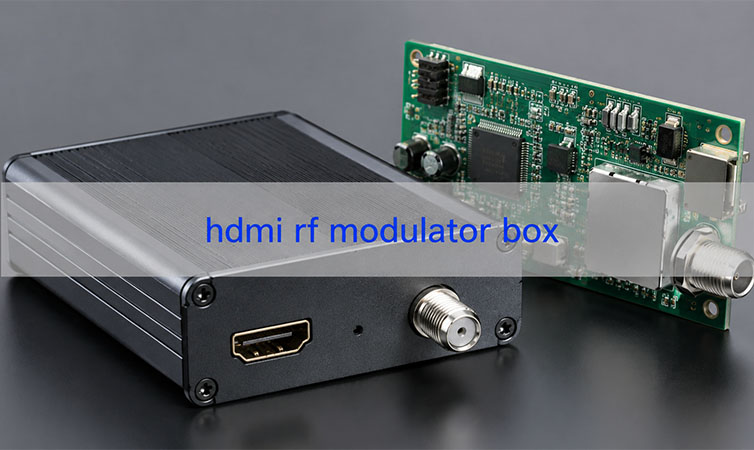
An HDMI RF modulator box looks simple from the outside. A user connects an HDMI source. Then the box sends the signal through a coaxial cable to a TV. However, the inside of the box is not simple. It needs a stable PCB, clean HDMI routing, strong RF output, and reliable PCBA assembly. It also needs good testing before shipment. For OEM brands, AV product companies, security system suppliers, and electronics manufacturers, this product is more than a converter. It is a mixed-signal electronic device. It combines HDMI, RF, power control, firmware, connectors, and enclosure assembly.
This guide explains the product from a PCB and PCBA manufacturing view. It also shows what buyers should check before prototype or mass production.
What Is an HDMI RF Modulator Box in PCB and PCBA Manufacturing?
An HDMI RF modulator box converts an HDMI signal into an RF signal. After that, the RF signal travels through a coaxial cable. A TV or RF distribution system can then receive the signal.
People often use this box with media players, cameras, DVRs, laptops, set-top boxes, and signage players. However, manufacturers need to look deeper. The real performance comes from the circuit board inside.
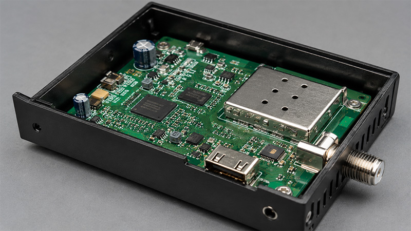
A typical PCBA may include:
- HDMI input circuit
- HDMI receiver chip
- Video processing IC
- RF modulator chipset
- Clock circuit
- Power management circuit
- Coaxial RF output connector
- MCU or control processor
- Buttons or display
- Shielding parts
- Test points
Each part has a clear job. The HDMI section receives the video signal. The processing section prepares the data. The RF section changes the signal into an RF channel. Then the coaxial output sends it to the cable.
Therefore, this type of product needs careful PCB design. It also needs accurate assembly and complete testing.
How Does an HDMI to RF Modulator Box Work at the Circuit Level?
An HDMI to RF modulator box follows a clear signal path.
- First, the HDMI input receives video and audio data. HDMI uses high-speed signals. So the PCB must keep these traces short and balanced.
- Next, the video processing circuit handles the signal. This area may include processors, memory, clocks, and firmware-controlled chips. It needs clean power and stable timing.
- Then, the RF modulator circuit changes the signal into an RF channel. This part needs strong layout control. For example, trace width, ground design, filters, and connector placement can affect RF quality.
- Finally, the coaxial output sends the signal to the cable. Many TV coaxial systems use 75-ohm impedance. So the PCB should keep the RF path stable.
Good circuit design is important. However, production quality also matters. Wrong parts, weak solder joints, or poor connector alignment can still cause problems. For this reason, the PCBA process must be controlled well.
What PCB Design Issues Affect an RF Modulator with HDMI Box?
An RF modulator with HDMI box has both digital and RF circuits. This makes PCB design more sensitive.
- First, HDMI traces need controlled impedance. The PCB stack-up affects this result. Copper thickness, dielectric thickness, trace width, and trace spacing all matter.
- Second, the RF section needs a strong ground path. A clean ground helps reduce noise. It also helps the RF output stay stable.
- Third, the PCB must control EMI. HDMI and RF circuits can both create noise. Therefore, engineers should plan filtering, shielding, and grounding early.
- Fourth, the board needs clean power. Different chips may need different voltage rails. In addition, RF circuits often need low-noise power. A stable power design helps the box work better.
- Finally, heat control matters. Many boxes are small. As a result, heat can build up inside the enclosure. Engineers can improve this with copper areas, thermal vias, and better component spacing.
A good PCBA manufacturer can review these points before production. This step helps reduce design changes later.
Why Does Signal Integrity Matter in an HDMI RF Modulator Box PCBA?
Signal integrity affects the real user experience. If the signal is poor, users may see image flicker, black screens, weak audio, or unstable channels.
In the HDMI section, engineers must control trace length, impedance, and spacing. They should also add proper ESD protection. These details help the box work with different HDMI sources.
In the RF section, the signal path should stay short and smooth. The layout should also keep a solid ground reference. Even small layout changes can affect output level and channel quality.
Clock circuits also need care. HDMI processing and RF modulation both need accurate timing. Therefore, oscillator placement and power filtering are important.
Assembly quality also affects signal performance. The manufacturer should control solder paste printing, component placement, reflow profile, and connector soldering.
However, visual inspection is not enough. The test team should also check HDMI input, RF output, audio, video, and channel settings. As a result, the final PCBA can perform better in real use.
What PCB Materials Are Used for a 4K HDMI RF Modulator Box?
A 4K HDMI RF modulator box handles more data than a basic model. It may also create more heat. Therefore, material choice matters.
Many designs use high-quality FR4. This material works well for many commercial HDMI and RF products. It also helps control cost.
However, some designs need better RF performance. In that case, engineers may choose low-loss RF materials. These materials reduce signal loss and offer better stability at higher frequencies.
Some products may also use a hybrid stack-up. For example, the main digital area may use FR4. The RF area may use a higher-grade RF laminate. This method can balance cost and performance.
When choosing PCB material, engineers should check:
- HDMI signal speed
- RF output frequency
- Modulation standard
- Board layer count
- Impedance control
- Heat control
- Product size
- Target cost
- Production volume
- Reliability needs
In addition, surface finish matters. ENIG, OSP, and other finishes suit different projects. The best option depends on soldering needs, shelf life, connector design, and budget.
Before production, the customer should discuss the material with the PCB manufacturer. This helps confirm that the board can support both performance and stable production.
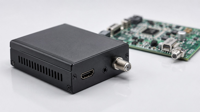
How Does an HDMI RF Modulator Coax Converter Box Handle RF Output?
An HDMI RF modulator coax converter box sends the final signal through a coaxial cable. This output section affects signal quality directly.
The RF output path usually includes the modulator circuit, filters, matching parts, and coaxial connector. These parts work together to control the final output.
Most TV coaxial systems use 75-ohm impedance. Therefore, the RF path should support this target where needed. The trace should also stay short and well grounded.
The connector also matters. Many products use F-type connectors. The connector must fit both the PCB and the enclosure. If it does not align well, it may stress the solder joints.
During box-build assembly, the manufacturer should check connector position, shell fit, screw holes, labels, and grounding. These checks help the final box feel solid and work well.
Useful production tests include:
- HDMI input test
- RF output test
- Channel setting test
- Video display test
- Audio output test
- Connector inspection
- Coax output stability test
- Sample aging test
As a result, the finished product can work better in homes, hotels, schools, security systems, and AV networks.
What Is the Difference Between HDMI to ATSC RF Modulator Box and HDMI to QAM RF Modulator Box?
An HDMI to ATSC RF modulator box and an HDMI to QAM RF modulator box both convert HDMI into RF. However, they serve different systems.
ATSC often supports digital TV broadcasting in North America. An HDMI to ATSC RF modulator box can create an ATSC-compatible RF channel. TVs that support ATSC can receive that channel.
QAM often appears in cable TV systems. An HDMI to QAM RF modulator box suits hotels, apartments, hospitals, campuses, and other multi-TV systems.
From a PCBA view, both products share similar sections. They need HDMI input, signal processing, RF modulation, power control, firmware, and coaxial output.
However, the chipset may differ. The firmware may also differ. In addition, the test method and output standard may change.
Before production, the customer should confirm:
- Target market
- TV standard
- Output channel plan
- Chipset solution
- Firmware process
- RF output level
- Test method
- Certification needs
Also, the BOM must stay clear and accurate. A wrong oscillator, filter, or RF part can affect performance. Therefore, careful BOM control helps keep each batch consistent.
How Are 4 Channel and 8 Channel HDMI to RF Modulator Box PCBAs Manufactured?
A 4 channel or 8 channel HDMI to RF modulator box is more complex than a single-channel model. It handles several HDMI inputs in one system.
Because of this, the PCB layout becomes denser. The power design also becomes more important. In addition, the enclosure must manage more heat.
For multi-channel products, engineers may use more PCB layers. A simple board may use 4 layers. However, a dense design may need 6 layers or more. More layers help with routing, grounding, and power distribution.
The BOM also needs strong control. Multi-channel boards use more HDMI connectors, processors, RF parts, clocks, filters, and passive parts. Therefore, the sourcing team must check part quality and delivery time.
During SMT assembly, accuracy is very important. Fine-pitch ICs, HDMI connectors, and small RF parts need stable process control.
Testing must also cover every channel. A board may power on, but one channel may fail. Therefore, the test plan should check each HDMI input and each RF output.
In addition, the box-build process should support heat control. The manufacturer may need thermal pads, vents, or metal housing contact.
For commercial AV products, this level of control brings better field performance. It also helps reduce installation issues.
How to Choose a PCBA Manufacturer for HDMI RF Modulator Box Production?
Choosing a PCBA manufacturer for this product takes more than price comparison. The project needs PCB knowledge, RF experience, sourcing ability, assembly control, and test support.
A good manufacturer should review the design before production. The review should cover PCB stack-up, impedance, RF layout, connector position, thermal design, and test points.
In addition, the manufacturer should support both PCB fabrication and PCBA assembly. This can reduce communication gaps. It also helps solve problems faster.
For this type of project, a suitable PCBA partner should support:
- DFM review
- PCB stack-up review
- Controlled impedance PCB fabrication
- RF PCB manufacturing
- Component sourcing
- BOM optimization
- SMT assembly
- Through-hole assembly
- HDMI connector assembly
- RF connector assembly
- AOI inspection
- X-ray inspection when needed
- Functional testing
- RF output test support
- Firmware loading
- Box-build assembly
- Final inspection and packing
EBest Circuit supports PCB fabrication, PCBA assembly, component sourcing, testing, and box-build assembly. The engineering team can also review Gerber files, BOM, assembly drawings, and test needs before production.
For RF and mixed-signal products, early review brings clear value. It helps improve manufacturability. It also helps reduce sourcing risk. Most importantly, it supports a smoother move from prototype to mass production.
To sum up, an HDMI RF modulator box depends on the PCB and PCBA inside. The outer shell matters, but the circuit board decides the real performance.
The design must handle HDMI signals, RF output, power stability, EMI control, heat, firmware, connectors, and enclosure fit. Therefore, OEMs should involve the PCBA manufacturer early.
With proper DFM review, controlled PCB fabrication, reliable sourcing, accurate assembly, and complete testing, the product can move from prototype to mass production more smoothly.
EBest Circuit supports PCB fabrication, PCBA assembly, component sourcing, RF-related assembly, testing, and box-build manufacturing for HDMI RF modulator box PCBA projects. For project review or quotation, please send Gerber files, BOM, and technical requirements to sales@bestpcbs.com.
FAQs About HDMI RF Modulator Box PCBA
What does an HDMI RF modulator box do?
It converts HDMI video and audio into an RF signal. Then the signal travels through coaxial cable to a TV or distribution system.
Is an HDMI RF modulator box only for home users?
No. Many OEM brands and AV product companies use this type of product for hotels, schools, security systems, and commercial TV networks.
Why does PCB design matter in this product?
PCB design affects HDMI quality, RF output, EMI control, heat control, and reliability. Therefore, layout quality has a direct effect on performance.
Can a 4K HDMI RF modulator box use FR4 PCB material?
Yes. Many designs can use FR4 when the stack-up and layout are well controlled. However, some RF designs may need low-loss materials.
What files are needed for PCBA quotation?
You can send Gerber files, BOM, pick-and-place file, schematic, assembly drawing, test plan, enclosure drawing, and order quantity.
Does this product need RF testing?
Yes. RF testing helps confirm output level, channel stability, and signal quality. Functional testing should also check HDMI input, video, audio, and settings.
Are 4 channel and 8 channel models harder to build?
Yes. They need better routing, stronger power design, more heat control, and full channel testing.
Can one manufacturer handle PCB, PCBA, and box-build assembly?
Yes. A one-stop manufacturer can support PCB fabrication, sourcing, SMT assembly, testing, enclosure assembly, labeling, and packing.
Tags: hdmi rf modulator box, hdmi rf modulators box, hdmi to rf modulator box
PakarPBN
A Private Blog Network (PBN) is a collection of websites that are controlled by a single individual or organization and used primarily to build backlinks to a “money site” in order to influence its ranking in search engines such as Google. The core idea behind a PBN is based on the importance of backlinks in Google’s ranking algorithm. Since Google views backlinks as signals of authority and trust, some website owners attempt to artificially create these signals through a controlled network of sites.
In a typical PBN setup, the owner acquires expired or aged domains that already have existing authority, backlinks, and history. These domains are rebuilt with new content and hosted separately, often using different IP addresses, hosting providers, themes, and ownership details to make them appear unrelated. Within the content published on these sites, links are strategically placed that point to the main website the owner wants to rank higher. By doing this, the owner attempts to pass link equity (also known as “link juice”) from the PBN sites to the target website.
The purpose of a PBN is to give the impression that the target website is naturally earning links from multiple independent sources. If done effectively, this can temporarily improve keyword rankings, increase organic visibility, and drive more traffic from search results.