MCPCB layout for automotive applications represents a highly demanding engineering task in terms of design and reliability. In the world of EVs, ADAS, and smart lighting, your board must endure thermal cycling from -40°C to 150°C and constant mechanical vibration. This guide provides actionable layout strategies to ensure your automotive MCPCB survives the rigors of the road.
EBest Circuit (Best Technology) is a dependable MCPCB manufacturer and assembly service provider based in China, recognized for our cutting‑edge technologies and rigorous quality benchmarks in MCPCB production and integration. Our expertise extends across automotive, aerospace, industrial control, and medical device sectors. We are committed to providing premium‑grade MCPCB products with efficient delivery cycles across all our services. Supported by state‑of‑the‑art production facilities and highly trained engineering professionals, we offer a comprehensive suite of electronics manufacturing solutions, supporting small batch productions. We accommodate projects of varying scales, covering automotive MCPCB layout, prototype development, and mass production. We’re happy to discuss your customized requirements at any time, and you may reach us at sales@bestpcbs.com.
What Is MCPCB Layout for Automotive Applications?
An MCPCB (Metal Core Printed Circuit Board) layout for automotive use is the specialized discipline of arranging circuitry on a thermally conductive substrate—usually aluminum or copper—to solve heat dissipation and mechanical stress issues inherent in vehicles. Unlike standard FR-4 boards used in consumer electronics, automotive MCPCBs serve as the backbone for high-power systems.
- Core Function: It functions simultaneously as an electrical circuit and a heat sink. The metal core (typically 1.0mm to 3.0mm thick) rapidly draws heat away from high-power components like LEDs, MOSFETs, and IGBTs.
- Key Applications: These layouts are critical in automotive LED headlights, Battery Management Systems (BMS), DC-DC converters, and motor controllers.
- Regulatory Compliance: A proper layout must account for AEC-Q100 standards, ensuring reliability under harsh environmental conditions including humidity, thermal shock, and mechanical vibration.
- Structural Difference: Unlike multilayer FR-4, the MCPCB layout typically consists of a thin dielectric layer (insulator) sandwiched between a copper circuit layer and a thick metal base.
Ultimately, mastering automotive MCPCB layout means understanding that the board itself is a thermal management system, not just a carrier for electronic components.
Why Does Thermal Management Matter Most in Automotive MCPCB Layout?
In automotive electronics, heat is the primary driver of failure. Poor thermal management leads to premature component death, color shift in lighting, and potential safety hazards. Here is why it dominates the layout process:
- Preventing Thermal Runaway: High temperatures increase the resistance of semiconductors, which in turn generates more heat. A well-designed layout breaks this positive feedback loop by providing a low-impedance thermal path.
- Ensuring Longevity: The Arrhenius equation dictates that every 10°C rise above the recommended operating temperature can halve the lifespan of an LED or electrolytic capacitor.
- Maintaining Optical Performance: In automotive lighting, excessive heat causes “color shift” (changes in Correlated Color Temperature) and lumen depreciation. Proper layout keeps the junction temperature (Tj) stable.
- Material Integrity: Excessive heat can cause the dielectric layer to delaminate from the metal core, leading to catastrophic electrical failure.
Consequently, prioritizing thermal pathways in your layout is the single most effective way to guarantee long-term reliability and prevent field failures.
How to Optimize Heat Dissipation in Automotive MCPCB Layout?
To maximize thermal performance, follow these layout best practices rooted in material science and physics:
- Calculate Trace Width Based on Current: Use the formula for current carrying capacity. For MCPCBs, a standard approximation is:
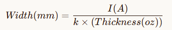
Where kis a constant (~0.024 for external layers).
- Implement Thermal Vias Strategically: Place an array of vias (e.g., 0.3mm diameter) directly under the thermal pad of high-power LEDs or MOSFETs. This creates a direct thermal bridge to the metal core.
- Adhere to Edge Clearance Rules: To prevent shorts during depaneling (V-cut or routing), maintain a safe distance. The rule is:
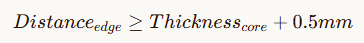
- Example: For a 1.5mm thick aluminum core, keep traces at least 0.75mm away from the board edge.
- Optimize Solder Mask Openings: Ensure the solder mask dam between pads is at least 0.2mm to prevent solder bridging while maximizing the exposed metal area for heat transfer.
Therefore, by combining precise calculations with strict adherence to spacing rules, you can create an efficient thermal highway that protects your components.
What Are the Key Layout Rules to Resist Vibration in Automotive MCPCBs?
Automotive environments subject electronics to constant mechanical shock (per ISO 16750). To prevent pads from lifting or traces from fracturing:
- Use Thermal Relief Connections (Cross-Hatch Pads): Never connect a pad directly to a large copper pour. Use a “star” or “cross-hatch” pattern. This reduces mechanical stress on the solder joint during thermal expansion and contraction cycles.
- Secure Heavy Components: Place inductors, transformers, and large connectors away from the board edges where vibration amplitude is highest. If they must be near the edge, provide additional mechanical support or adhesive.
- Maintain Drill-to-Edge Distance: Holes are structural weak points. Maintain a distance from the hole edge to the board edge equal to the material thickness.
- Example: For a 2.0mm thick core, keep holes at least 2.0mm from the edge.
- Correct Drill Diameter Selection: For aluminum substrates, the drill diameter must match the thickness to avoid tool breakage.

- Data Point: A 2.0mm thick aluminum core requires a minimum drill diameter of 1.02mm.
In summary, designing for vibration requires a balance between electrical connectivity and mechanical flexibility to withstand the constant physical stress of the road.
How to Ensure High-Voltage Safety in Automotive MCPCB Layout?
Safety is non-negotiable. Your layout must prevent arcing and ensure galvanic isolation between high-voltage (HV) and low-voltage (LV) circuits:
- Creepage and Clearance Distances: Follow standards for insulation. For primary (high-voltage) to secondary (low-voltage) circuits, maintain a minimum creepage distance of 6.4mm. If space is limited, cut a slot in the solder mask or dielectric to increase the surface path length.
- Silkscreen Labeling for Safety: Use clear markings for polarity and high-voltage warnings. The minimum character height should be 1.52mm with a width of 0.38mm. Keep characters at least 0.254mm away from pads to avoid interfering with soldering.
- Grounding Strategy: Use a single-point ground for analog/digital separation to prevent ground loops, which can introduce noise in sensitive BMS measurements.
Thus, integrating safety margins and clear labeling into your layout is essential for preventing electrical hazards and meeting stringent automotive certifications.
Which Components Need Special Layout Attention in Automotive MCPCBs?
Different components have unique layout requirements that impact overall system reliability:
- Power LEDs (Lighting): Ensure uniform current distribution. Use symmetrical trace routing to prevent current crowding. For high-power LEDs, place thermal vias directly under the die attach pad.
- MOSFETs and IGBTs (Power Stages): Minimize the high-current loop area. Keep the connection between the switch, inductor, and input capacitor as short and wide as possible (using the 2oz/0.23mm or 3oz/0.3mm rules).
- Connectors: Ensure connectors are placed at least
material thicknessaway from the board edge. For frequently mated connectors, add strain relief or mechanical locking features.
Specifically, tailoring your layout approach to the specific needs of power devices, LEDs, and connectors ensures optimal performance across the entire system.
What Are the Top 5 Mistakes to Avoid in Automotive MCPCB Layout?
Avoid these common pitfalls that lead to manufacturing delays or field failures:
- Violating Edge Clearance: Placing traces closer than
material thickness + 0.5mmfrom the edge risks short circuits during V-cutting.
- Incorrect Drill Sizes: Using a 0.5mm drill on a 2.0mm aluminum core will break tools. Always match drill diameter to material thickness.
- Skipping Thermal Relief: Direct connection of pads to large copper planes causes “pad lifting” during reflow due to differential thermal expansion.
- Ignoring Silkscreen Spacing: Putting text over pads or vias makes inspection and rework impossible.
- Underestimating Creepage: Failing to provide 6.4mm clearance between HV and LV traces can cause arcing and fire hazards.
Ultimately, avoiding these five critical errors will save significant time and cost in both the prototyping and mass production phases.
How to Validate Your Automotive MCPCB Layout for Real-World Performance?
Before sending your design to production, validate it thoroughly to ensure it meets both thermal and mechanical demands:
- Run a Comprehensive DRC (Design Rule Check): Verify against MCPCB-specific rules:
- Minimum line width: 0.2mm (1oz), 0.23mm (2oz), 0.3mm (3oz).
- Minimum line spacing: Same as width rules above.
- Annular ring: Ensure sufficient copper around drilled holes.
- Perform Thermal Simulation: Use software (like Ansys Icepak or Flotherm) to calculate junction temperatures (Tj). Ensure Tjstays below the component’s maximum rating (e.g., 125°C for most LEDs).
- Conduct Mechanical Stress Analysis: Verify that your layout complies with vibration profiles (e.g., 10-2000Hz random vibration). Pay special attention to large components and connector mounts.
- Collaborate with Your Manufacturer Early: Share your stack-up and layout with your MCPCB fabricator. They can verify that your drill sizes (e.g., 1.57mm for 3.0mm thick aluminum) and edge clearances are manufacturable.
In conclusion, rigorous validation and early collaboration with your manufacturing partner are the final steps to transforming a theoretical layout into a reliable automotive product. By following these design principles, you can develop an automotive MCPCB layout that features exceptional stability, consistent performance, and full suitability for large‑scale manufacturing. Our engineering team excels at enhancing design solutions for superior thermal management and anti‑vibration performance. We’re happy to provide professional project evaluations and optimization suggestions, and you can contact us at sales@bestpcbs.com.
FAQs About MCPCB Layout For Automotive
1. What is the difference between “thermal” and “electrical” layers in a thermoelectric separation MCPCB layout for automotive?
In thermoelectric separation MCPCB layouts for automotive applications, the “thermal” layer refers to dedicated thermal pads designed exclusively for heat dissipation, while the “electrical” layer consists of electrode traces that conduct current. These two layers are physically isolated by an insulating dielectric (such as BT or FR4 material) to prevent short circuits. This separation optimizes thermal management (critical for high-power LEDs or power modules) without compromising electrical performance.
2. What is the minimum via diameter required for double-sided aluminum MCPCB layouts in automotive applications?
For double-sided aluminum MCPCB layouts in automotive applications, the minimum via diameter is 0.5mm. This specification ensures reliable plating and structural integrity, as smaller diameters may lead to poor conductivity or breakage during thermal cycling or vibration—common stressors in automotive environments.
3. Why is green film preferred as the backside protective film for aluminum MCPCB layouts in automotive use?
Green film is the preferred backside protective film for aluminum MCPCB layouts in automotive applications because it is heat-resistant. Unlike blue, white, or red films, green film withstands high-temperature processes (e.g., reflow soldering, thermal curing) without degrading, ensuring the metal core remains protected during manufacturing and operation.
4. How does boss height tolerance impact automotive MCPCB layout reliability?
In automotive MCPCB layouts, the boss height tolerance must be ≤0.05mm. This tight tolerance ensures consistent contact between the thermal pad (on the panel) and the metal core (substrate), minimizing thermal resistance. Excessive tolerance could create air gaps, reducing heat dissipation efficiency and increasing the risk of component failure under automotive thermal stress.
Tags: automotive mcpcb manufacturer, custom automotive mcpcb layout, iatf16949 certified mcpcb, MCPCB Layout For Automotive, thermal management mcpcb, vibration resistant mcpcb
PakarPBN
A Private Blog Network (PBN) is a collection of websites that are controlled by a single individual or organization and used primarily to build backlinks to a “money site” in order to influence its ranking in search engines such as Google. The core idea behind a PBN is based on the importance of backlinks in Google’s ranking algorithm. Since Google views backlinks as signals of authority and trust, some website owners attempt to artificially create these signals through a controlled network of sites.
In a typical PBN setup, the owner acquires expired or aged domains that already have existing authority, backlinks, and history. These domains are rebuilt with new content and hosted separately, often using different IP addresses, hosting providers, themes, and ownership details to make them appear unrelated. Within the content published on these sites, links are strategically placed that point to the main website the owner wants to rank higher. By doing this, the owner attempts to pass link equity (also known as “link juice”) from the PBN sites to the target website.
The purpose of a PBN is to give the impression that the target website is naturally earning links from multiple independent sources. If done effectively, this can temporarily improve keyword rankings, increase organic visibility, and drive more traffic from search results.