A fusible resistor is a protective resistor that provides normal resistance control while adding a controlled open-circuit function under overload. When current or heat exceeds its rated limit, it disconnects the circuit path instead of continuing to burn, drift, or damage nearby components.
To use a fusible resistor correctly, it is important to understand its working principle, material structure, resistance value, markings, color code, datasheet parameters, identification method, testing process, selection rules, and replacement steps. This guide explains each part in a clear order, so the correct fusible resistor can be identified, verified, selected, and replaced with fewer mistakes.
What Is a Fusible Resistor?
A fusible resistor is a protective resistor that combines resistance control and fail-safe circuit protection in one component. Under normal operation, it works like a resistor by limiting current, dividing voltage, or supporting circuit stability. When abnormal current exceeds its rated limit, it opens the circuit safely like a fuse.
This component is widely used in power supplies, adapters, LED drivers, chargers, home appliances, audio equipment, and IoT circuit board assemblies. Its main function is not only to provide a resistance value, but also to reduce the risk of overheating, burning, or secondary circuit damage.
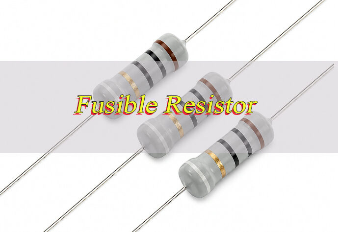
A fusible resistor may look similar to a normal resistor, but its internal structure and safety behavior are different. It is usually designed to fail in a controlled open-circuit mode instead of burning continuously or creating a short circuit.
Why Is a Fusible Resistor Important?
A fusible resistor is important because it helps protect circuits from overcurrent, short-circuit faults, surge stress, and abnormal load conditions. In compact electronic products, one failed component can affect the whole board, so controlled failure is critical.
In many power input sections, the fusible resistor is placed near the AC input, DC input, rectifier circuit, or switching power area. When a fault occurs, it can disconnect the current path before heat spreads to surrounding components.
It also helps reduce board-level risk in high-density assemblies. For IoT circuit board products, compact layouts, wireless modules, power ICs, sensors, and charging circuits often share limited space. A properly selected fusible resistor improves safety and product reliability without taking much board area.
How Does a Fusible Resistor Work?
A fusible resistor works in two stages: normal resistance mode and protection open-circuit mode.
- During normal operation, current flows through the resistor element.
- The resistor provides its rated resistance value, such as 1 Ω, 10 Ω, 47 Ω, or 100 Ω.
- If current rises above the safe limit, the resistor heats rapidly.
- The fusible element reaches its failure point.
- The resistor opens the circuit and stops current flow.
- The circuit is protected from further overheating or component damage.
The key point is that a fusible resistor is designed to fail safely. A normal resistor may overheat, discolor, crack, or continue burning under severe fault conditions. A fusible resistor is made to open the circuit under defined overload conditions.
What Are Fusible Resistors Made Of?
Fusible resistors are usually made from metal oxide film, wire wound elements, ceramic cores, flame-retardant coatings, and conductive end caps. The exact construction depends on power rating, package type, and application.
A metal oxide fusible resistor is common in power circuits because it has stable resistance, good heat tolerance, and reliable overload behavior. It is often used in adapters, power boards, and control circuits.
A fusible wire wound resistor uses resistance wire wound around a ceramic or insulating core. This type is suitable for higher power applications and surge-prone circuits. It is often found in power supplies, industrial boards, and equipment with stronger current loads.
An SMD fusible resistor uses a compact surface-mount structure. It is suitable for space-limited PCB assemblies, including IoT circuit board modules, compact chargers, sensor products, and communication boards.
What Is the Value of a Fusible Resistor?
The value of a fusible resistor refers to its resistance rating, usually measured in ohms (Ω). Common values include 1 ohm fusible resistor, 10 ohm fusible resistor, 47 ohm fusible resistor, and 100 ohm fusible resistor.
The correct value depends on the circuit position and protection target. A low-value fusible resistor may be used for current sensing, inrush limitation, or input protection. A higher-value fusible resistor may be used in signal paths, startup circuits, or voltage-dropping sections.
When selecting a fusible resistor value, the following parameters should match the original circuit requirement:
- Resistance value
- Power rating
- Tolerance
- Voltage rating
- Fusing behavior
- Package size
- Temperature rating
- Flame-retardant grade
Replacing only by resistance value is not enough. For example, a 10 ohm normal resistor and a 10 ohm fusible resistor may show the same resistance on a multimeter, but their overload behavior is different.
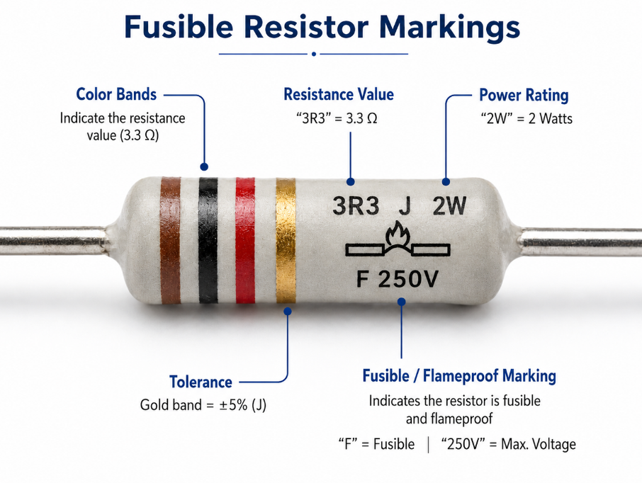
What Are the Markings on a Fusible Resistor?
Fusible resistor markings help identify resistance value, tolerance, package type, and sometimes safety characteristics. Through-hole fusible resistors often use color bands, while SMD fusible resistors commonly use printed numeric codes.
Common marking types include:
- Color bands for axial through-hole fusible resistors
- Three-digit SMD code for standard surface-mount values
- Four-digit SMD code for higher precision values
- Letter suffixes for tolerance or series information
- Body color or coating type for flame-retardant identification
- Datasheet part number for exact electrical behavior
Some fusible resistors may not have a clear “fusible” label on the body. Therefore, visual appearance alone is not reliable. The safest method is to confirm the part number, board position, circuit function, and datasheet details.
What Is the Color Code for a Fusible Resistor?
The fusible resistor color code usually follows standard resistor color code rules. The first bands show resistance value, the multiplier band shows the number of zeros, and the tolerance band shows allowable variation.
Common examples include:
| Color Code | Value | Tolerance |
|---|---|---|
| Brown Black Gold Gold | 1 Ω | ±5% |
| Brown Black Black Gold | 10 Ω | ±5% |
| Yellow Violet Black Gold | 47 Ω | ±5% |
| Brown Black Brown Gold | 100 Ω | ±5% |
However, color code alone does not confirm fusible function. A normal resistor and a fusible resistor may share the same color bands. The circuit location, datasheet, flame-retardant coating, and original BOM information should be checked before replacement.
How to Calculate Fusible Resistor Color Codes?
Fusible resistor color code calculation can be done with the same method used for standard resistors. The key is to calculate resistance first, then confirm whether the component is truly fusible.
Step-by-step method:
- Identify the first color band.
- Identify the second color band.
- Check the multiplier band.
- Multiply the first two digits by the multiplier.
- Read the tolerance band.
- Confirm the part type from datasheet or circuit position.
Example:
A resistor marked brown, black, black, gold means:
- Brown = 1
- Black = 0
- Black multiplier = ×1
- Gold tolerance = ±5%
- Final value = 10 Ω ±5%
For SMD fusible resistor parts, use the printed marking instead of color bands. For example, 100 usually means 10 Ω, while 101 means 100 Ω. Always verify the marking rule from the component series because some manufacturers use special codes.
What Are the Types of Fusible Resistors?
Fusible resistors are classified by structure, package, and circuit use. The right type depends on power rating, surge stress, board space, and mounting method.
- Metal Oxide Fusible Resistor
Provides stable resistance, heat resistance, and flame-retardant performance. It is commonly used in adapters, LED drivers, power input circuits, and control boards. - Fusible Wire Wound Resistor
Uses resistance wire wound around an insulating core. It supports higher power and stronger surge conditions, making it suitable for power supplies and industrial circuits. - Fusible Film Resistor
Offers stable performance in a compact structure. It is used in consumer electronics, compact modules, and PCB assemblies requiring controlled open-circuit failure. - SMD Fusible Resistor
Designed for surface-mount assembly and space-saving layouts. It is suitable for IoT circuit board assemblies, chargers, sensor modules, and communication boards. - Through-Hole Fusible Resistor
Uses leaded terminals and is easier to inspect, test, and replace. It is often used in power boards, appliances, and repairable electronic products. - Low-Ohm Fusible Resistor
Values such as 1 ohm fusible resistor and 10 ohm fusible resistor are used for input protection, current limiting, startup paths, and surge-related circuits. - Medium-Value Fusible Resistor
Values such as 47 ohm fusible resistor and 100 ohm fusible resistor are used in control circuits, voltage-dropping paths, and protection networks.
What Is a Fusible Resistor Used For?
A fusible resistor is used in circuits where resistance control and fault protection are both required. It is commonly placed in positions where overcurrent may occur due to short circuits, surge voltage, component failure, or wrong input conditions.
Common applications include:
- Power supply input protection
- AC/DC adapter circuits
- LED driver protection
- Battery charger circuits
- Home appliance control boards
- Audio amplifier circuits
- IoT circuit board power sections
- Industrial control modules
- Sensor and communication boards
In these applications, the fusible resistor helps protect the circuit before a fault spreads. It is especially valuable in boards where compact size, stable operation, and controlled failure behavior are required.
What Is the Difference Between a Fusible Resistor and a Normal Resistor?
A fusible resistor provides resistance and opens the circuit during abnormal overload. A normal resistor mainly controls current or voltage and does not provide the same controlled protection.
The key difference is failure behavior. A fusible resistor is designed to fail as an open circuit under overload. A normal resistor may overheat, burn, drift, crack, or continue conducting under fault conditions.
| Item | Fusible Resistor | Normal Resistor |
|---|---|---|
| Main Function | Resistance + circuit protection | Resistance only |
| Failure Mode | Opens circuit under overload | May overheat, burn, or drift |
| Protection Role | Used in safety-related positions | Used in general circuit paths |
| Common Location | Power input, startup circuit, surge path, protection circuit | Signal path, divider circuit, bias circuit, general load |
| Replacement Rule | Match resistance, power, package, and fusible behavior | Match resistance, tolerance, and power |
| Overcurrent Response | Disconnects under abnormal current | No guaranteed protection response |
| Flame-Retardant Construction | Common in fusible series | Depends on resistor type |
| Selection Risk | Wrong type weakens protection | Wrong value affects circuit function |
A normal resistor should not replace a fusible resistor in protection positions. Even if the resistance value is the same, the overload behavior may be completely different.
What Are the Advantages of Fusible Resistors?
Fusible resistors offer practical benefits in board-level protection and production reliability.
- Two functions in one component: Provides resistance and fault protection.
- Controlled failure behavior: Opens the circuit under abnormal current.
- Space saving: Reduces extra protection components in compact boards.
- Wide value range: Available in 1 Ω, 10 Ω, 47 Ω, 100 Ω, and many other values.
- Multiple packages: Available in SMD and through-hole formats.
- Improved safety: Helps reduce overheating and secondary damage.
- Useful for compact products: Suitable for IoT circuit board and small electronic assemblies.
These advantages make fusible resistors suitable for protection circuits where board space, safety, and stable operation must be balanced.
What Are the Limitations of Fusible Resistors?
Fusible resistors also have limits. They should be selected according to real circuit conditions instead of being treated as universal protection parts.
- One-time protection: Once blown, the part must be replaced.
- Limited current range: Not suitable for every high-current fault condition.
- Selection sensitivity: Wrong power rating may cause false failure or weak protection.
- Heat influence: Poor thermal layout can affect reliability.
- Not a full fuse replacement: It cannot replace every fuse application.
- Datasheet matching required: Fusing time and overload behavior vary by series.
A fusible resistor should be treated as a safety-related component. The resistance value, power rating, overload curve, mounting method, and circuit position should all be checked before final selection.
Fusible Resistor Datasheet Overview
A fusible resistor datasheet should be checked before selection, replacement, or production approval. It confirms the electrical value, package, safety behavior, and overload performance.
| Datasheet Item | What to Check |
|---|---|
| Resistance Value | 1 Ω, 10 Ω, 47 Ω, 100 Ω, or required custom value |
| Tolerance | ±1%, ±2%, ±5%, ±10% |
| Rated Power | 1/8W, 1/4W, 1/2W, 1W, 2W or higher |
| Maximum Working Voltage | Rated voltage limit |
| Fusing Characteristic | Fusing current, overload level, and fusing time |
| Overload Rating | Short-time overload capacity |
| Temperature Range | Operating and storage temperature |
| Temperature Coefficient | Resistance change under temperature variation |
| Package Size | SMD size, body size, or lead spacing |
| Mounting Type | SMD or through-hole |
| Coating Material | Flame-retardant coating, ceramic body, or insulated coating |
| Soldering Condition | Reflow, wave soldering, or hand soldering limits |
| Safety Approval | UL, RoHS, or other applicable compliance |
| Failure Mode | Open-circuit behavior under overload |
| Manufacturer Series | Exact product family and datasheet series |
The most important items are resistance value, rated power, fusing characteristic, package size, and failure mode. Two fusible resistors with the same ohm value may behave differently during overload, so datasheet comparison is required before using an alternative part.
How to Identify a Fusible Resistor?
A fusible resistor should be identified through circuit position, markings, appearance, and datasheet confirmation. Visual inspection alone is not enough because many fusible resistors look similar to normal resistors.
1. Check the PCB Reference Designator
Look near the component label on the board. Fusible resistors may be marked as FR, RF, F-R, R-F, fusible resistor, or similar codes. However, markings vary by manufacturer, so the reference designator should be used as a clue, not final proof.
2. Check the Circuit Location
Fusible resistors are often placed near power input areas, rectifier circuits, switching power supplies, startup circuits, LED driver inputs, or charger protection sections. If the resistor is close to the input power path, it may have a protection role.
3. Read the Body Marking
Through-hole types may use color bands. SMD fusible resistors may use 3-digit or 4-digit codes. Record the marking clearly before removal because burned components may become harder to read later.
4. Inspect the Component Body
Many fusible resistors use flame-retardant coating, ceramic bodies, or special insulating layers. Some may appear gray, blue, green, or white depending on series. Body color can help, but it cannot confirm the part alone.
5. Compare with BOM or Schematic
The BOM or schematic is the most reliable identification source. Check whether the part description includes fusible resistor, flameproof resistor, safety resistor, metal oxide fusible resistor, or fusible wire wound resistor.
6. Search the Part Number
If a manufacturer code or series number is visible, compare it with the datasheet. Confirm resistance, tolerance, power rating, package, and fusing behavior.
7. Check Failure Condition
A failed fusible resistor may show cracks, discoloration, burn marks, or open-circuit behavior. Some fail internally with no visible damage, so electrical testing is still required.
8. Confirm Before Replacement
Do not replace the part only by size or resistance. Confirm that the replacement has the same fusible function and suitable safety behavior.
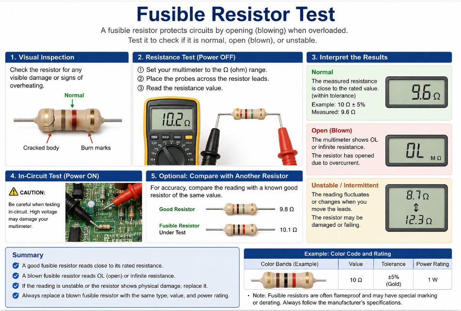
How to Test a Fusible Resistor?
A fusible resistor is usually tested with a digital multimeter. The purpose is to confirm whether it is normal, open, drifted, or damaged. Before testing, power must be fully removed from the circuit.
1. Disconnect Power Completely
Remove all power sources before testing. For power supply boards, chargers, and high-voltage circuits, wait until the circuit is safe to handle.
2. Discharge Capacitors
Large capacitors may hold charge after power is removed. Discharge them safely before touching the board or measuring resistance.
3. Inspect the Resistor Visually
Check for cracks, burn marks, coating damage, lifted pads, darkened PCB areas, or damaged nearby components. Visible damage often indicates overload or a downstream short.
4. Set the Multimeter to Resistance Mode
Select the appropriate ohm range. For low-value parts such as 1 ohm fusible resistor, use a low-resistance range if available.
5. Measure Across Both Terminals
Place probes on both ends of the resistor. A normal part should read close to its rated resistance within tolerance.
6. Compare with the Rated Value
Compare the measured value with the marking or datasheet. For example, a 10 ohm fusible resistor with ±5% tolerance should be close to 10 Ω.
7. Check for Open Circuit
If the meter shows OL, infinite resistance, or no continuity, the fusible resistor is likely blown.
8. Check for Resistance Drift
If the value is much higher than rated, the resistor may be heat-damaged or aged. Drifted parts should be replaced because protection and circuit performance may be unreliable.
9. Lift One Side if the Reading Is Unclear
In-circuit measurement may be affected by parallel components. If the reading does not make sense, desolder one side and test again.
10. Check Downstream Components
If the fusible resistor is blown, test rectifier diodes, MOSFETs, capacitors, ICs, load circuits, and power rails. A blown fusible resistor is often caused by another failed component.
11. Test After Replacement
After installing a new fusible resistor, check resistance again. Then power the circuit carefully, preferably with current limitation, and monitor temperature and voltage.
How to Choose the Right Fusible Resistor?
Choosing the right fusible resistor requires matching electrical value, protection behavior, package, and operating environment. Resistance value alone is not enough.
- Match the Resistance Value
Use the same resistance value as the original part, such as 1 Ω, 10 Ω, 47 Ω, or 100 Ω. A different value may change current flow, voltage drop, startup behavior, or protection response. - Match the Power Rating
The rated power must support normal operation without overheating. A lower power rating may fail too early. A much higher rating may delay protection and reduce safety performance. - Confirm the Fusible Characteristic
The replacement must be a true fusible resistor. It should open safely under overload instead of burning or shorting. - Check the Fusing Time
Different series open at different overload levels and time ranges. Choose a part with fusing behavior close to the original datasheet. - Match the Package Type
Use the correct package, such as SMD or through-hole. For SMD parts, match pad size and package code. For through-hole parts, match lead spacing and body size. - Check the Working Voltage
The resistor must support the circuit voltage under normal use. Insufficient voltage rating can cause breakdown or unsafe operation. - Check the Temperature Rating
Select a resistor that can operate under the product’s thermal conditions. High-temperature environments require stronger thermal stability. - Review Tolerance Requirements
Tolerance affects circuit accuracy. For protection positions, ±5% or ±10% may be common, but the original circuit requirement should be followed. - Confirm Flame-Retardant Construction
For input power and safety-related positions, flame-retardant coating or certified safety construction is important. - Check Assembly Compatibility
Confirm reflow, wave soldering, or hand soldering conditions. Wrong soldering temperature can damage the resistor before the product is used. - Avoid Unknown Substitutes
Unknown parts may have unstable fusing behavior. Use verified parts with clear datasheets and consistent supply. - Confirm Application Fit
Power supplies, LED drivers, chargers, industrial boards, and IoT circuit board assemblies may require different resistor structures. Select the type based on actual circuit stress, not only part appearance.
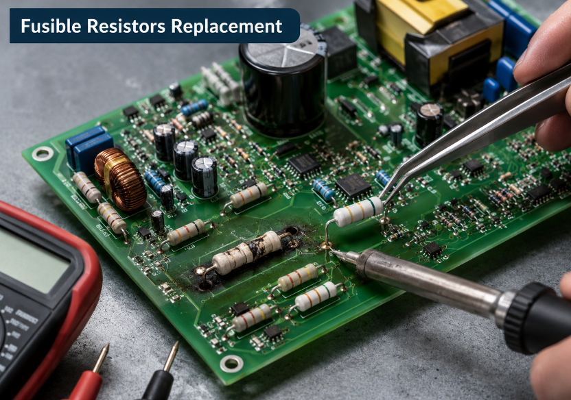
How to Replace Fusible Resistors?
A fusible resistor should be replaced only after checking the cause of failure. If the original fault remains, the new resistor may blow immediately.
- Turn Off and Isolate Power
Disconnect the board from all power sources. For high-voltage circuits, confirm that no dangerous voltage remains. - Discharge Stored Energy
Discharge capacitors safely before touching the circuit. This is especially important for power supply boards and charger circuits. - Record the Original Part Information
Take a photo of the resistor position, marking, body color, and nearby components. Record resistance value, package type, and board reference code. - Confirm the Original Specification
Check the BOM, schematic, or datasheet. Confirm resistance, power rating, tolerance, package, voltage rating, and fusible behavior. - Inspect the Surrounding Circuit
Look for damaged diodes, capacitors, MOSFETs, ICs, dark PCB areas, cracked solder joints, or shorted loads. - Test for Short Circuits
Before removing the resistor, check downstream resistance to ground or across power rails. A shorted circuit must be repaired before installing a new part. - Remove the Failed Resistor
Use proper soldering or desoldering tools. Avoid pulling the part by force because this may lift pads or damage traces. - Clean the Pads
Remove old solder and residue. Inspect the pads and copper traces for heat damage or lifting. - Install the Correct Replacement
Use a replacement with the same fusible function and matching electrical specifications. Do not use a normal resistor in a protection position. - Control Soldering Heat
Apply suitable soldering temperature and time. Excessive heat may damage the resistor or weaken the pads. - Inspect the Solder Joints
Check for solder bridges, cold joints, poor wetting, or misalignment. For SMD parts, confirm both terminals are properly soldered. - Measure the Installed Resistor
Check resistance after installation. The reading should match the expected value unless parallel circuit paths affect the measurement. - Power Up Carefully
Use current-limited power when possible. Monitor input current, output voltage, and resistor temperature. - Confirm Stable Operation
If the new fusible resistor heats abnormally or fails again, stop testing and inspect the fault circuit again. - Document the Replacement
Record the replacement part number and test result. This helps maintain consistency during repair, production, or future sourcing.
FAQs About Fusible Resistors
Q1: Is a power resistor the same as a fusible resistor?
A1: No. A power resistor is made to handle higher power dissipation, while a fusible resistor is made to open the circuit under abnormal overload. Some fusible resistors can also be power-rated, but the two terms are not the same.
Q2: Can I replace a fusible resistor with a normal resistor?
A2: No, not in safety-related positions. A normal resistor may match the same ohm value, but it does not provide the same controlled open-circuit protection. The replacement should match resistance, power rating, package, and fusible behavior.
Q3: What is the difference between fusible resistor and fuse?
A3: A fuse is mainly used to break the circuit during overcurrent. A fusible resistor provides resistance during normal operation and also opens during overload. It combines current control and fault protection in one component.
Q4: How do I know if a fusible resistor is blown?
A4: Use a multimeter in resistance mode. If the reading shows OL, infinite resistance, or a value far above the rated range, the fusible resistor is likely blown or damaged.
Q5: Can a fusible resistor fail without visible burn marks?
A5: Yes. Some fusible resistors open internally without obvious body damage. Visual inspection is useful, but resistance testing is more reliable.
Q6: Are fusible resistor color codes the same as normal resistor color codes?
A6: Usually yes for resistance value. However, color bands only show resistance and tolerance. They do not always confirm fusible behavior. Datasheet confirmation is recommended.
Q7: What does a 1 ohm fusible resistor do?
A7: A 1 Ω fusible resistor may be used for input protection, inrush limitation, or current-related protection paths. Its exact role depends on the circuit position and power rating.
Q8: What should be checked before replacing a blown fusible resistor?
A8: Check for shorted diodes, MOSFETs, capacitors, ICs, damaged traces, and wrong input voltage. A blown fusible resistor often indicates another fault in the circuit.
Conclusion
A fusible resistor is a small but important safety component in electronic products. It provides resistance during normal operation and opens the circuit during abnormal overload. Correct identification, testing, and replacement help improve board reliability, reduce repeat failures, and protect surrounding components.
EBest Circuit provides component sourcing and PCB assembly service with fusible resistors. For stable quality, matching specifications, and reliable order support, contact sales@bestpcbs.com to get a professional quotation and start your fusible resistor order with EBest.
Tags: Fusible Resistor Color Code, Fusible Resistor Function, Fusible Resistor Markings, Fusible Resistor Replacement, Fusible Resistor Value
PakarPBN
A Private Blog Network (PBN) is a collection of websites that are controlled by a single individual or organization and used primarily to build backlinks to a “money site” in order to influence its ranking in search engines such as Google. The core idea behind a PBN is based on the importance of backlinks in Google’s ranking algorithm. Since Google views backlinks as signals of authority and trust, some website owners attempt to artificially create these signals through a controlled network of sites.
In a typical PBN setup, the owner acquires expired or aged domains that already have existing authority, backlinks, and history. These domains are rebuilt with new content and hosted separately, often using different IP addresses, hosting providers, themes, and ownership details to make them appear unrelated. Within the content published on these sites, links are strategically placed that point to the main website the owner wants to rank higher. By doing this, the owner attempts to pass link equity (also known as “link juice”) from the PBN sites to the target website.
The purpose of a PBN is to give the impression that the target website is naturally earning links from multiple independent sources. If done effectively, this can temporarily improve keyword rankings, increase organic visibility, and drive more traffic from search results.